
Inspiration: Prusa i3 MK2 / MK3
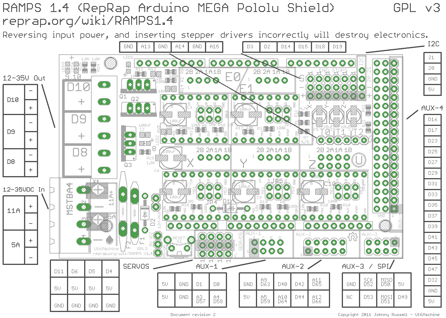
As you might know, the RAMPS board has only 3 switchable 12V connections that are usually occupied by: Hotend, part cooling fan, heated bed. The Prusa i3 MK2 and MK3 both toggle their hotend fan at around 40-50°C so they only turn on when the hotend reaches that temperature and turn off when it has cooled down below that.
I always liked this feature when I saw it on the printers at my FabLab; it’s just so much more elegant than the behaviour of my old 3D printer: Sometimes I sit at my desk, the print is done and I hear the very loud (I should switch to a Noctua on that printer..) fan noise from the other room for another 30 minutes until I realize it’s actually already done and cooled down to room temperature! At that point, I walk over, turn the printer off, wait a bit more for the build plate to cool off and then I can take the part off.
On the other hand, at the FabLab the printers sit there, turned on ready to go all the time and totally silent when not actually in use. This is great, that’s the way all printers should behave in my opinion so I needed to get this feature on my new MK3 as well.
Chris Riley’s guide
I quickly found out that Chris Riley, who I’ve mentioned before had made a video about this topic, which you can find here: Auto Hotend Fan Using RAMPS - Chris’s Basement. His circuit is perfectly fine, even though the explanation is not completely correct (see video description / comments), but it has no impact on the end result in this case.
The idea is basically just to use a transistor to toggle the negative connection of the fan to ground. The signal comes from any free pin on the RAMPS (e.g. from AUX-1 / servo pins) and the power ideally comes from the little male connector on the board (labeled 12V-AUX, top left of the reset button). If you don’t have that connector, I’d really recommend soldering one on as I don’t like Chris’ solution of “piggybacking” the 12V from the already problematic PSU connector.
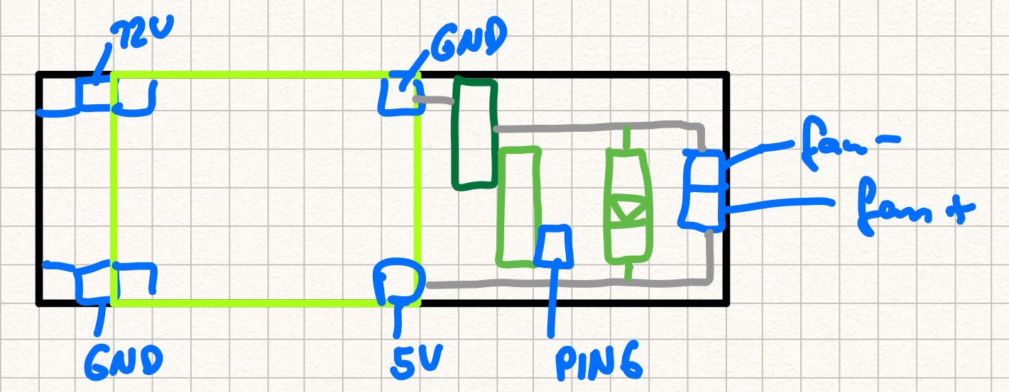
Here you can see an image of my approximate PCB layout - not very professional, but I think a lot cleaner than what was shown on the vieo and creating this helped me a lot while soldering.
 |
 |
|---|---|
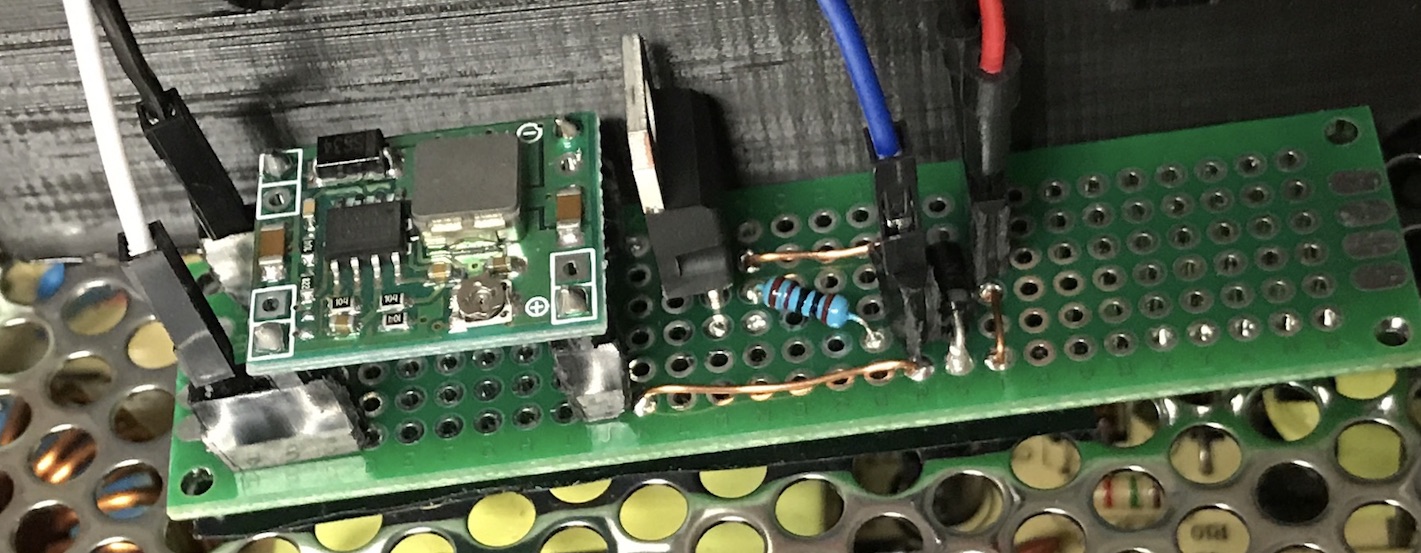
| PCB layout | Actual circuit |
Note that I have a 12-to-5V buck converter, because I unfortunately bought the wrong fan (“MK3 version”) that needs 5V supply voltage.
I also used female connectors for most stuff so that I can easily disconnect or connect something if needed. But: it’s very dangerous, because you do NOT want this fan to turn off while the hotend is hot! It will probably melt the carriage, fall onto the heatbed, might catch fire…. So this is NOT the configuration I’ll be running my prints with! Either the wires are going to be glued onto the connectors with hot glue, or maybe soldered on, we will see - especially because I still need to figure out how I’ll organize the electronics (don’t fit the original case because of TMC2130) and the setup of this little extra board definitely also depends a lot on the enclosure that I will use.